Once upon a time, I set out to see whether I could do an entire mixed-signal design using nothing but a CY8CKIT-049-42xx PSoC® 4 Prototyping Kit with its PSoC® 4200 MCU chip (the CY8C4245AXI-483). These kits were available for the insanely attractive price of $4USD for a complete development environment: hardware and IDE software — you just plugged them into your computer’s USB port to program them! Sadly, they are no longer available (the “replacement”, the CY8CKIT-043 PSoC® 4 M-Series Prototyping Kit, has the more feature-rich PSoC® 4200M and costs a whopping $10USD… still a bargain and a half, fyi). The challenge to myself was to use nothing but the MCU’s on-chip features, with the exception of some passives for filtering and such. One of the things I wanted to do was to play a very short audio clip (in a loop, or built dynamically from pieces); however, the PSoC® 4200 doesn’t have a proper digital-to-analog converter (DAC). It has two current DACs (IDACs) that are there to support the capacitive touch-sensing functionality, but they are both low resolution and I did want to use the touch sensing so was hopeful I could save them for that purpose. Enter pulse-width modulation (PWM). I had read about it being used for audio applications, but had never tried it for myself, and set out to do just that. It required much in the way of experimentation, simulation, and trial and error, but I eventually got it working to my satisfaction. Seeing a believable and reasonably low distortion 1kHz sine wave being generated by the MCU with a few resistors and capacitors, after so much gnashing of teeth and banging of head, made it worth the effort. I am writing here on how I did it since it’s a fairly general technique that can be used in many applications.
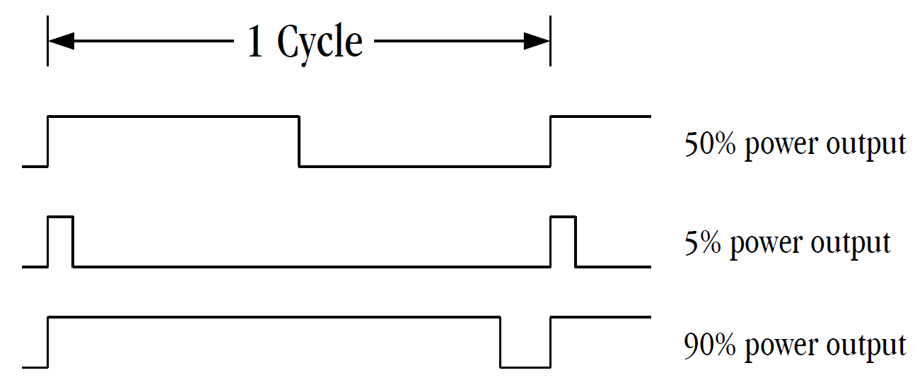
I am assuming a general familiarity with PWM (and if you are familiar, skip this paragraph and the next), and there are a lot of great resources online, but just in case you’re not familiar with it, pulse width modulation is a way of using a digital signal to deliver a variable amount of power to a “load” (e.g. LED, motor, or audio amplifier in this case). The more traditional way of delivering varying power is to change the voltage and/or current going to the load, but since we only have the on/off states of a digital signal, we need to turn to another variable: time. If a digital signal is on 100% of the time, it delivers an amount of power to the load, let’s say an amount of 1 arbitrary unit of power (to make it concrete, say the voltage on the digital output is 3.0V and it is providing 10mA of current to an LED, then the maximum power it can deliver to the LED by being on 100% of the time is 3.0V x 0.010A = 30mW… it can’t be any more “on” than “on all the time”). Conversely, if the digital signal is on 0% of the time (that is to say, off all the time), then it will deliver 0 units of power to the load (with the LED example, this would be 0mW of power). Now, let’s say the digital signal is on 50% of the time, it will be delivering 0.5 units of power to the load (back to the LED, this would be 15mW). How does this work? Well, for 50% of the time, it will be delivering 1 unit of power; and for the other 50% of the time, it will be delivering 0 units of power. The total amount of power delivered over one on/off cycle is going to be power delivered during the amount of time during the cycle it is on, plus the power delivered during the amount of time the cycle it is off. For the 50% on case, it’s 1 unit * 0.5 + 0 units * 0.5 = 0.5 units of power per cycle (for the LED, this would be 30mW * 0.5 + 0mW * 0.5 = 15mW). The same holds for any proportion of on vs. off. For 5% on vs. 95% off this is 1 unit * 0.05 + 0 units * 0.95 = 0.05 units of power to the load (for the LED example: 30mW * 0.05 + 0mW * 0.95 = 1.5mW). For 90% on vs. 10% off this is 1 unit * 0.9 + 0 units * 0.1 = 0.9 units of power (for the LED: 30mW * 0.9 + 0mW * 0.1 = 27mW). Thus, the pulse is being modulated (changed with time) by changing the width of the on portion of the pulse, and so “pulse width modulation” (PWM). To be more technical, the amount of power delivered is the integral of the time-varying power over one on/off cycle.
The catch with PWM is that the cycle time needs to be short enough (which is the same as saying that the frequency needs to be high enough) that whatever system being controlled with a PWM signal doesn’t have time to react in any appreciable way to the on then off nature of the cycle, but reacts slowly enough that the system being driven with a PWM signal integrates the pulses into the time-averaged power you are trying to deliver to the system. If you drive an LED with a 1kHz PWM signal and use a photodiode hooked up to an oscilloscope to “look” at the LED, you will see the on/off pulses very clearly. However, if you look at that same LED with your eyes, they can’t react that fast and will therefore “integrate” the optical output power of the LED. You will not be able to tell that the LED is actually flashing with your eyes, it just looks brighter or dimmer depending on the duty cycle of the PWM signal being applied to the LED. If you drive it with a 0.1Hz cycle (cycling every 10 seconds) you will be able to clearly see the LED going on and off with your eyes. Consider a motor now. If the cycle time of the PWM is too slow, the motor will race at full speed during the on portion of the PWM signal, and be unpowered (and probably still moving at a fair clip) during the off portion of the PWM signal. If you’re trying to have the motor turn at a controllable variable speed, this is obviously not the way to do it. Thus, the cycle time needs to be short enough that the motor doesn’t have time to react to the discrete on vs. off portions of the cycle and properly integrates (or smooths) the power being delivered to it. A larger, heavier, motor will react slower and can tolerate a longer cycle time since its inertia will smooth out its motion; but a smaller, lighter, motor will react faster and needs a shorter cycle time since it doesn’t have as high an inertia to smooth out the on/off switching. Finally, for audio applications, if you drove a speaker directly with a PWM signal with a short enough cycle time, you could use the inertia of that speaker to integrate that PWM signal and get a high quality audio output with as little distortion as you wanted. Another way to integrate the PWM signal into a passable audio signal is to use a low pass filter, which is the solution used for this project. A low pass filter can be thought of as providing an inertia to fast changing signals (such as the on/off switching of the PWM presuming it’s switching fast enough), and so it effectively integrates the output power so we get the output signal we want (the average power rather than the on/off switching of the signal). As an aside, “Class-D” amplifiers use this technique as well: they drive a PWM signal with a suitably low cycle time into a low pass filter and then into your speakers. This technique achieves very high efficiencies (thus low power dissipation in the amplifier itself versus in the speaker where we want the power to go). Wikipedia has a good article on Class-D amplifiers if you’re interested. For audio, it is ultimately the human ear that is the arbiter of what works and what doesn’t.
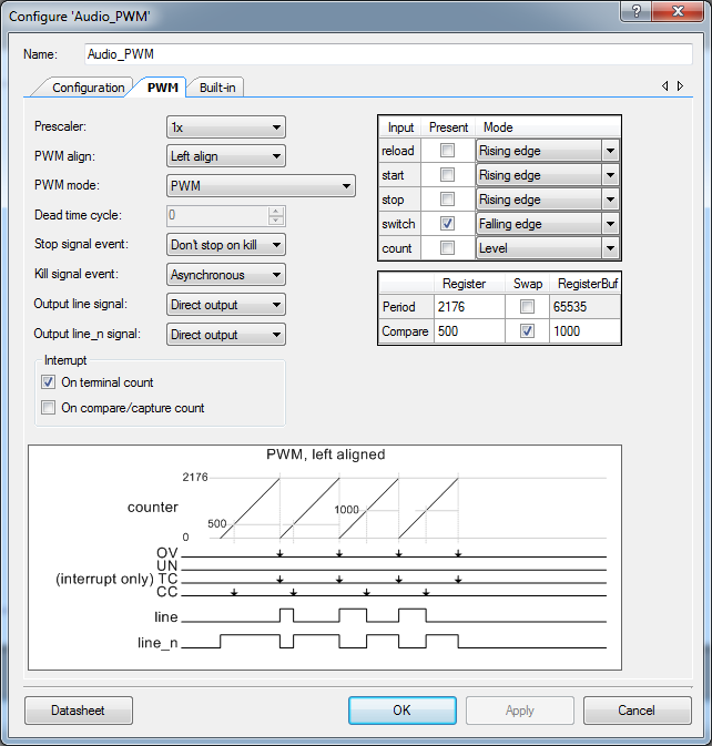
The PSoC® 4200 chip on the development kit I was using has 4 dedicated high-speed “Timer/Counter/PWM” units (called “PWM (TCPWM mode)” in the PSoC Creator™ Component Catalog), so it was a no-brainer to choose to use that built-in functionality for this project. The datasheet for it is available from Cypress here: PSoC 4 Timer Counter Pulse Width Modulator (TCPWM). I won’t go into details here on how to wrangle PSoC Creator™, but under the Configuration tab select the “PWM” option and the second tab will become “PWM”. I named the instantiation “Audio_PWM”. Here’s a screen capture of the configuration I used. Again, without going into the details of the implementation since this is a generic technique, I clocked the TCPWM unit with the full 48MHz internal clock of the PSoC® 4200 with no prescaler (1x). The Period Register of the PWM is set to 2176, which means the period is 2177 clocks, which works out to 22048.69Hz or about 22.05kHz. CD quality audio is 44.1kHz, so this number is no accident as it is exactly half of that (give or take a bit) so I could keep any audio conversion I wanted to do at common audio data rates (not entirely necessary, but why go too far off track if without good reason).
The way the PSoC® 4200 PWM works is the Line Output stays high while the count is less than the value in the Compare Register, then goes low from when the Compare Register is equal to the counter until the counter is reset back to 0 on the next clock after the “terminal count” (TC, the value in the Period Register) is reached. Because I needed to load in a new value to be output each cycle (the next sample from the audio data), the “swap” flag is turned on so the Compare Register Buffer is enabled. At the end of each cycle, if a hardware “switch” event has occurred, the values of the Compare Register and Compare Register Buffer are swapped. If the next audio sample is loaded into the Compare Register Buffer before the terminal count is reached, it gets loaded automatically by the hardware into the Compare Register which is used for the upcoming cycle. This pipelining of sample values makes it a lot easier to drive the hardware from the CPU firmware because it just needs to be able to load the next value within 2177 clocks, which it can easily do… even waking up from a sleep state. How it does this is a little tricky though. Firstly, the “interrupt” output of the TCPWM is connected to a PSoC Creator™ Interrupt component, which generates a hardware interrupt to the CPU subsystem on, in this case, the rising edge of the “interrupt” signal from the TCPWM (which will also rouse the CPU out of a basic sleep state if necessary). The interrupt service routine fetches the next audio sample that needs to be output and writes it into the Compare Register Buffer so that it’s ready for the swap at the end of that cycle. That part is pretty easy. Note however that the “switch” input is turned on and is set to be active on a falling edge. I connected the overflow (“ov”) output of the TCPWM component back to the “switch” input. So after the end of each cycle, the overflow output outputs a short pulse that is then detected on the switch input, and which generates a switch event. Once the switch event occurs, the TCPWM is primed to do the register swap at the end of the cycle (but won’t do the swap otherwise). Since this happens every cycle, it does a swap at the end of every cycle, just before the CPU gets the interrupt and writes the next sample into the Compare Register Buffer. The audio waveform thus gets written and converted into the corresponding PWM pattern and output via the Line Output signal, which is my case goes directly to an output pin on the PSoC® 4200 and then the low pass filter. As an aside, I was playing around with the PWM component to make sure everything I said above was accurate (it wasn’t in my first draft, fyi), and ran into some problems I had to ask for help with before I could resolve them. You can find that thread here if you end up trying to use the PSoC® 4200 PWM component yourself. Just to preserve it here: a better solution is to loop the Inverted Line Output to the “switch” input rather than the overflow output as this will work for any PWM clock frequency, where my solution only works if you clock the PWM at the HFCLK frequency of the PSoC® 4200 (thanks to Motoo Tanaka on the Cypress Community Forums for their very elegant solution).
Before I can move on to how the audio is recorded, encoded, processed, decoded, and played back, I need to talk about the low pass filter circuit and the sampling rate. You will note that I said the PWM cycle frequency was 22.05kHz, but this is actually quite misleading. Yes, the PWM frequency I used really is 22.05kHz, but my audio sampling frequency is half that again, or really 11.025kHz. The maximum audio signal frequency that can be reproduced is one half of the sampling frequency, or in this case about 5.5kHz. The human voice produces frequencies between 80Hz and 14kHz, but traditional phone lines only permitted frequencies between 300Hz and 3.4kHz. So, a maximum frequency of 5.5kHz still gives better audio quality than a telephone call would, and that was good enough for me, and that is why I chose the audio sampling frequency of 11.025kHz. Consider for a moment that half that sampling frequency (~5.5kHz) would only allow for an audio bandwidth of ~2kHz, which would be worse than a telephone audio channel, so 11.025kHz was as low as I wanted to go for this application. The trick with the audio filter on the output is then to let as much of the 5.5kHz pass through while blocking any frequencies higher than that (since they will be artifacts of the sampling, and not real audio data). When I first tried this circuit, I clocked the PWM at 24MHz (half the frequency of the PSoC® 4200’s highest system clock frequency) and really did have the cycle frequency of the PWM at 11.025kHz. I had to lower the cutoff frequency of the low pass filter to try and block the very audible 11.025kHz squeal of the PWM frequency, and the audio sounded terrible and the squeal still hurt my ears and gave me a headache. I was about to throw in the towel on the whole idea when I a brain fart and doubled the frequency of the PWM cycle to 22.05kHz, and then just sent the same sample to the PWM twice so I would still be sending audio samples to it at 11.025kHz. This worked like a charm and I could use an output filter with quite easy to achieve performance since the PWM cycle frequency was already nearly ultrasonic. It still needed the filter for sure though (for anti-aliasing to be technical) because I was still sending sampled audio, but it was much easier since the higher frequency was so well and easily attenuated. I will talk a little more about the filter circuit, and the problems this posed by using the PSoC® 4200’s built-in op-amps at the end of this post, but that’s enough to move forward now.
Heading back to the question of audio, after the audio sampling rate had been chosen there were a few decisions that needed to be made. The first question is what encoding technique I was going to use? To keep things simple, I decided to use linear pulse-code modulation (PCM) which simply represents the sampled audio waveform at each point on a linear scale from the lowest possible sampled amplitude to the highest. This is the same encoding used for CDs and such, and requires no processing overhead to decode the audio data before being able to send the actual value of a sample to be output. There are other PCM encoding techniques that use non-linear scales (e.g. logarithmic compression μ-law or A-law) to achieve higher dynamic range at the cost of loss of accuracy of reproduction in some cases, or adaptive differential pulse-code modulation (ADPCM) that can achieve higher levels of compression and was used for voice channels in digital telephony. All of these require calculations or lookup tables to extract the linear samples needed for playback from the encoded and/or compressed data. Compression techniques like MP3 and its ilk are way too complicated for what I needed to do. So… keeping it simple: linear PCM for this project. The question became then: how many bits of resolution should I aim for? I have used 8-bit samples before and they work, but they don’t make for great audio, so that would be the minimum I thought I could get away with. What is the maximum number of bits I could use? In looking at the PWM period count, that would be something less than 2177 (this was the highest I could go at the sampling frequency I wanted because I was clocking at the highest frequency possible for this MCU, so there was nowhere to up up from there). The highest 2^n number less than 2177 is 2048, and that gives 11 bits of resolution, which is pretty good (CD quality is 16 bits). I chose to move forward with 11-bit resolution, and ended up sticking with that for the project. The more bits per sample (and the higher the sampling frequency), the more memory is needed to store the audio samples. I probably could have gone down to about 8kHz for the sampling frequency in a pinch (it would give about telephone-grade audio quality) and shaved about 38% off the needed memory, or dropped the resolution down to 8 bits and shaved another 38% off, but it turned out I didn’t need to (and so kept the audio quality as high as I could). The PSoC® 4200 I was using has 32KiB of flash memory (which is the maximum for that family of MCUs). Presuming I used 10KiB of memory for the program, this left 22KiB of flash memory for the audio data (again, I was trying to use only the resources available in the PSoC® 4200 to see what it could do). 22KiB is 22528 bytes, which is 180224 bits. 180224 bits / 11 bits per sample = 16384 samples. 16384 samples / 11025 samples per second = 1.49 seconds of audio data. I needed 1.35 seconds to 1.40 seconds, so again this was barely sufficient for my purposes… but my clip would play in a loop, and could do so for as long as needed. I hope you’re not too disappointed in such a paltry number, but these are small chips with limited internal capabilities, and it was just enough for me. If that’s too cramped, you can buy 8MiB serial (SPI) flash chips for under $4.00CAD in single quantities and have at it (which would give just over 9 minutes of linear PCM audio at 11-bit/11.025kHz quality on a single chip, or about twice that if you dropped the resolution and sampling frequency to the bare minimum, and even more if you used some form of audio compression).
There are likely a nearly infinite number of ways of getting audio into the necessary format, but here’s what I did. I recorded my source audio at 44.1kHz (CD quality) in stereo using the open source audio recording and editing program Audacity. Once recorded, I converted the audio to mono from stereo to start. There was no particular value in doing the initial recording in stereo other than having good source material for other potential uses later. For the purposes of this project, a single-channel mono recording would have worked just as well. I then used Audacity‘s Normalize effect to both remove any DC bias from the audio track, and normalize the track to -1.0dB (0dB is the maximum possible value without causing clipping of the waveform). At this point, you can do any editing you want to do to make it sound the way you want. Effects like compression can reduce the volume variation in the sample and make it sound more even (I didn’t use any). Filtering can be used as well since anything above 5.5kHz in this design will not be reproduced properly. I did some filtering, but it didn’t make much of a difference to the audio quality because of the audio I was using, which is good. This also allows you to preview what the audio will actually sound like on a set of hopefully better speakers or headphones than will be driven by the PWM. If it sounds bad at this stage, more work probably needs to be done on the audio before continuing. The next thing I did was to then edit down the audio file to just the bit of the audio I needed (the “clip”). I used simple fades at the start (fade in) and end (fade out) of the clip to get rid of the usual clicks or pops when looping an untreated clip. If you want to be fancy, or simple fades don’t sound great (you can loop in the clip in Audacity to hear what it sounds like looped), you can do an overlapping crossfade so the audio at the end of the clip overlaps a bit with the audio at the beginning. There are lots of tutorials on how to do that, but I didn’t have to go that far, it sounded fine with the simple fades for my clip. I then used the Change Tempo effect to crunch my clip down just a little bit to 1.35s without altering the pitch (my clip was just a bit too long and this was an easy fix and sounded okay).
I then did something that I look back on as being a somewhat weird decision: I used Audacity to effectively convert the audio clip from 16-bits dynamic range, to the target 11-bit dynamic range. It probably did a very nice job of it and I think I would do it this way again, but I had forgotten I had done this until I looked at my audio conversion code and realized that it expected, in the 16-bit samples it was reading, no value outside of an 11-bit range. This evidently simplified the software I had to write by doing it at this stage of the process. Because Audacity is all about audio quality, I suspect the result is better than if I’d done the conversion to 11-bits from 16-bits myself. The process is very simple: the total number of possible values in a 16-bit sample is 65536, and the total number for an 11-bit sample is 2048, so just convert the ratio into decibels and apply that level of normalization. This calculation can be done with the formula: dB = 20 * log_10(Vout/Vin). Here, Vout and Vin are arbitrary, but the ratio is still 2048/65536. Using my handy-dandy calculator, 20 * log_10(2048/65536) = -30.103dB. So, as long as the audio is normalized to something lower than -30.103dB (say, -30.5dB or -31.0dB, which is probably what I did), then the dynamic range will have been reduced to at most 11-bits. Once I did that last normalization, I exported the audio to a standard signed 16-bit PCM/WAV file.
For the next step, I used the open source and amazing (if overly complex, flexible, and sometimes inscrutable) tool ffmpeg to convert the files from signed 16-bit 44.1kHz WAV files into signed 16-bit 11.025kHz RAW format files (which contains just the samples, no container or other meta information). This took a surprisingly long time to figure out how to do (the documentation is no help, I found some notes by searching the net), but the command line I used is:
ffmpeg -i infile.wav -f s16be -ar 11025 -ac 1 -c:a pcm_s16be outfile.raw
The “-f s16be” option indicates that the format should be forced to 16-bit signed big-endian values (which are a lot easier to work with in my opinion versus the little endian format you usually get on a PC, Linux or otherwise, and translate well to the MCU environment). The option “-ar 11025” indicates the audio rate or audio sampling frequency for the output (11.025kHz in this case, ffmpeg will downsample). “-ac 1” indicates the output should have 1 channel (mono). And “-c:a pcm_s16be” specifies that the “pcm_s16be” audio codec be used to trancode to the output file. The suffix “.raw” on the output file indicates to ffmpeg that it should use no container for the output file (just save the raw signed 16-bit big-endian samples in a file with no headers or meta data). In this minimal format, I could write a program to read that file with some simple code, manipulate it in any way I wanted to, and then save it in my own format. The ability to save audio data into a format I could easily manipulate with my own software is a sufficient result in and of itself to have justified the project to this point!
I wrote two small programs in C to get the data into a format I could use optimally on the MCU, and easily from within PSoC Creator™. The first program read in the RAW audio data as generated by ffmpeg and output it in an “encoded” audio format of my design (where “design” is overstating the case, it’s a trivial format and the only one that makes sense). If I had not effectively converted from 16-bits to 11-bits at the audio editing stage with Audacity, I would have had to do that in this program as well. It can be tricky to do nicely, so I’m glad I let the developers for Audacity write the algorithms to scale the audio amplitude. Because I am using the PWM component to output the waveform, and it will only accept unsigned values, I first needed to do that conversion. In thinking about the requirements to drive the PWM, the question needs to be asked: what is PWM zero from an audio perspective? Since audio waveforms oscillate around a zero amplitude value (which is actually 0 in a signed audio waveform), the “0 value” for our 11-bit unsigned sample needs to be in the middle of its range as well, or 1024 in this case (1/2 of 2048). As an aside, a signed 11-bit number can have values from -1024 to +1023 (0 takes up one of the 2048 possible values in the signed number). So adding 1024 to it converts it from a signed number with its “zero” at 0, to an unsigned number with its “zero” at 1024. But since I am counting to from 0 to 2176 (2177 clock cycles) for the PWM cycle to get the sampling frequency I want, those 2048 values should be centered around the middle of the PWM counting range, and that middle value is 1088 (since it’s an odd number of cycles, 1088 is exactly in the middle). Since the “zero” of the unsigned 11-bit sample is 1024 and the midpoint of the PWM count is 1088, to convert from the 11-bit sample value to the PWM compare register value, just add 1088 – 1024 = 64 to it on the MCU (which will be part of the code in the interrupt service routine to fetch the next 11-bit sample and write a value into the PWM Compare Register Buffer). So the range of PWM values with an 11-bit dynamic range centred on the PWM’s mid-point count will be from 64 to 2111. This means that to generate “silence” with the PWM (what would have been sample values of 0 for the signed samples), we are running it at a duty cycle of 50%, and the audio is generated by modulating the duty cycles to either side of 50% to recreate the audio signal. It does mean that the “0 value” for this circuit is actually at 50% power, so there is a common-mode voltage generated at 50% of the supply voltage of the MCU. The audio filter and audio amplifier should also operate at that same common mode voltage (which makes sense if they’re powered with the same single-ended power supply as is used for the MCU), or an AC coupling capacitor in series with the signal can be used to allow the common mode voltage further down the audio path to be set by component in the chain after it (the amplifier I used after the audio filter had an AC coupling capacitor on its input and ran off a +12V supply). I should mention that this issue of common-mode voltage is the reason why it is important to remove the DC offset of any audio samples used in this way (I used Audacity to do this): so the common-mode voltage is not drifting all over the place, but is, on average, held near a single value.
Back to the first program I wrote, because I had already reduced the audio amplitude to be no more than 11-bits of dynamic range, I just had to read in each 16-bit signed value from the RAW audio file (they are just one after the other in the file), add 1024 to that signed value, and poof, the result was always positive and thus unsigned. Fyi, my code did check to make sure no value was over 2047 or less than 0 after the addition of 1024, just to make sure I had done my normalization calculation right, and would bail if even a single sample was out of range. When it was done running, it also output the minimum and maximum sample values so I could check to make sure I hadn’t reduced the dynamic range to, say, 10 bits or something (checking I had not been over-aggressive with my audio normalization parameter). After the sample was converted to an unsigned 11-bit PCM value, my software packed it tightly into a memory array that I was treating as a bucket of bits (a bit stream array) so that the MSB of the new sample started in the bit immediately after the LSB of the previous sample in the bit array. When it was done, in my program’s memory, I had a long array of bits that contained my tightly-packed 11-bit PCM samples that I would then write to my encoded audio data file. As an aside, since the bits were stored in bytes on disk and in memory (I used the uint8_t data type internally), if there were any bits left to fill in the last byte, I just wrote 0s into them. Once it was loaded into flash memory on the MCU, it was the interrupt handler’s job to pull the next sample out of this bit stream in its memory and write it into the Compare Register Buffer before the next terminal count event in the PWM component (2177 clock cycles). It also needed to ignore any bits in the last byte that didn’t have valid data in it (easy to do because there wasn’t 11 more bits to pull out of the array, but I had to think about how this would all work). The PSoC® 4200’s ARM Cortex-M0 processor (running at 48MHz as well) was completely up to the challenge.
So I now had a big bag of bits (packed unsigned 11-bit PCM samples) on the disk in my encoded audio data file, and I needed to be able to program it into the MCU with PSoC Creator™. So I wrote another program that just took the encoded file’s bytes and wrote them out in a comma-separated list, one per line, and then used the C preprocessor to load them into a data structure in memory. I have yet to think of a better way of doing this, and I’ve used this technique in other places that required large data structures to be coded in C (and the ASCII version of the bytes doesn’t have to be pretty, it is only being read by the C compiler). Here are the first few lines of a data file for the compiler built from an encoded audio data file, and then the C in my PSoC Creator™ “main.c” code to load it for the compiler. Keep in mind for the data file that these are encoded unsigned 11-bit samples in a bit stream that has been cut into 8-bit chunks and output as numbers to be read by the compiler. For instance, the first three numbers are 127, 240, and 2 (3 8-bit bytes = 24 bits) and these encode the first two 11-bit samples (22 bits) and the two MSBs of the next sample (2 bits). So the first sample is “011 1111 1111” or 1023 (which would have been -1 in the original signed sample), the second sample is “100 0000 0000” or 1024 (which would have been 0 in the original signed sample), and the first two bits of the next sample are “10”. Note, that the first couple of samples being near audio “zero” (1024 for our unsigned 11-bit samples) makes sense because I did use the fade function at the start to eliminate pops and clicks at the loop boundaries.
First few entries in an “audio.dat” file (ASCII format numbers, comma separated, one value per line):
127,

240,

2,

0,

64,

8,

1,

0,

32,

3,

etc.
The code to load the data file into a C memory array is easy (to be programmed into flash memory on the MCU):
#include <stdint.h>

const uint8_t audio_data [] = {

#include "audio.dat"  // Put comma separated values audio samples file here

};
And that’s it. Our tiny little MCU now has audio data ready for playback on a PWM component! I have described all of the bits and pieces of software, firmware, and some hardware on how to implement a full system from start to PWM output. While having to use a PWM digital circuit as my “digital to analog” converter is specific to my goal of buiding this using nothing but the components on the PSoC® 4200 that is on the CY8CKIT-049-42xx PSoC® 4 Prototyping Kit, everything I’ve described about actually getting audio samples into an MCU is applicable to any similar application. In particular, a lot of MCUs (including ones from Cypress) have proper Digital-to-Analog converters (DACs) built in and can go directly from a sample to an analog output without all the fuss of the PWM. But those are going to be single-ended devices as well and will need unsigned samples just like the PWM that will be fed to it by an interrupt service routine or a on-chip DMA capability. Once the samples are packed into the flash memory on a processor, it’s relatively straightforward to get it out… getting it there, as you can see, is a bit of a chore the first time (after that it’s not so bad).
What I haven’t really described above is what exactly happens in my system (the CY8CKIT-049-42xx) after the PWM is happily chugging out sample data. The short story is that I used the two on-chip op-amps on the PSoC® 4200 to build a 4th order Chebychev low pass filter with the two amplifiers in a Sallen-Key configuration with a 1kHz cutoff frequency using resistors and capacitors. I am not going into details here (that’s for another post), but one snag to keep in mind is that buried in the op-amp’s DC Specification is that the maximum capacitive load (Cload) is only 125pF! This messed me up early on because I used much larger capacitors in the filter circuits like I would use with other op-amps, and they just wouldn’t work. When I redid the circuits with 100pF capacitors in the feedback loop instead (which required quite large resistor values to compensate), things worked much better (and it does a fine job of filtering out the PWM cycle noise). The other thing that I would like to grumble about, is that Cypress does not provide a SPICE simulation model for their on-chip op-amp. I tried to pick an existing model that might have approximated its behaviour, but it was nowhere close. In fact, the performance of the on-chip op-amps isn’t that good for an op-amp, and a real model would have been a great help in designing that part of the circuit. If I find the time, I may attempt to do a proper characterization of it myself (there’s not quite enough information in the datasheet to build a SPICE model), and I can write a post about that process. Perhaps. For the audio amplifier to drive the speaker, I bought a CK153 7W mono amplifier kit from my local electronics hobby shop (remember those?) that was made by a company called CanaKit. It was based on the TDA2003 amplifier chip, which is one that I was interested in trying. In the end, the TDA2003 needs +12V and the PSoC® 4200 runs off +3.3V to +5.0V, so that is sub-optimal. I ended up powering the overall circuit from +12V, and then using a little DC-DC converter module I bought from China to supply the +5V. Going forward, I would definitely try to pick an audio amplifier that ran off the same voltage as the MCU.
Note: After sharing this article, I received a request on the Cypress Community Forum to post a demo project, so I put one together that outputs a continuous 1kHz sine wave. This project is available there and on the Open Hardware resources page on this site where it is called the “Alebo PSoC® 4200 PWM Audio Demo Project”.
PSoC® and PSoC Creator™ are trademarks of Cypress Semiconductor Corporation.
Photo credit: “Ice On Branches”; Ottawa, Canada. © 2018, P. Friar. Used with permission.